|
|
|
Research
|
Magnetic Resonance Imaging
|
|
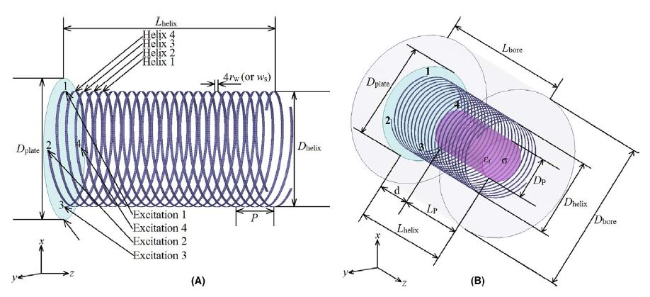
Design sketches of the helical-antenna RF coil: a quadrifilar (four-helix) traveling-wave antenna fed by four phase-shifted excitations (left), and the full computational model showing how the coil wraps around a patient-mimicking phantom inside a metallic MRI scanner bore (right). |
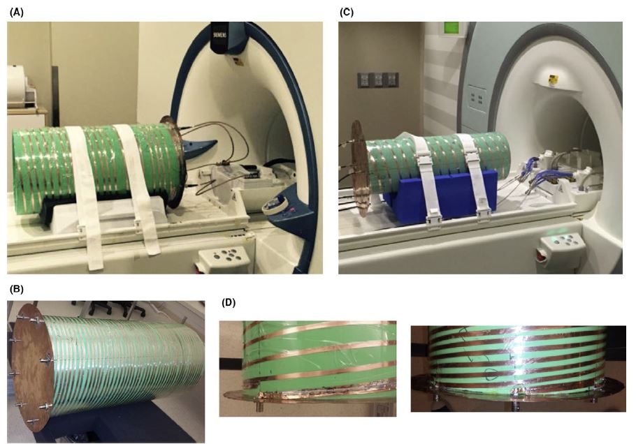
| Fabricated multi-channel helical-antenna coil prototypes mounted inside actual 7-Tesla and 10.5-Tesla MRI scanners at the University of Minnesota's Center for Magnetic Resonance Research, including close-ups of the custom impedance-matching plates that tune each helix. |
|
|
|
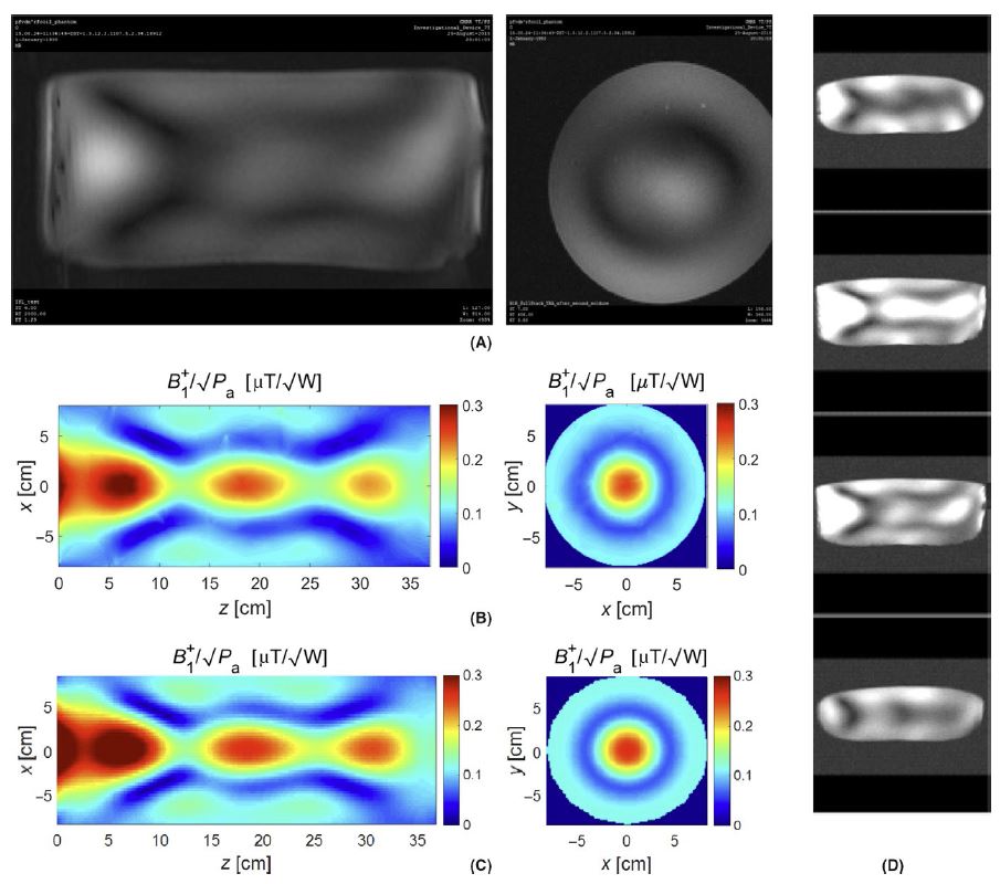
Side-by-side comparison of measured and simulated magnetic field (B1) maps for the 4-channel coil, showing excellent agreement between two independent computational methods and real scanner measurements — validating the design before it's relied on for actual patient imaging. |
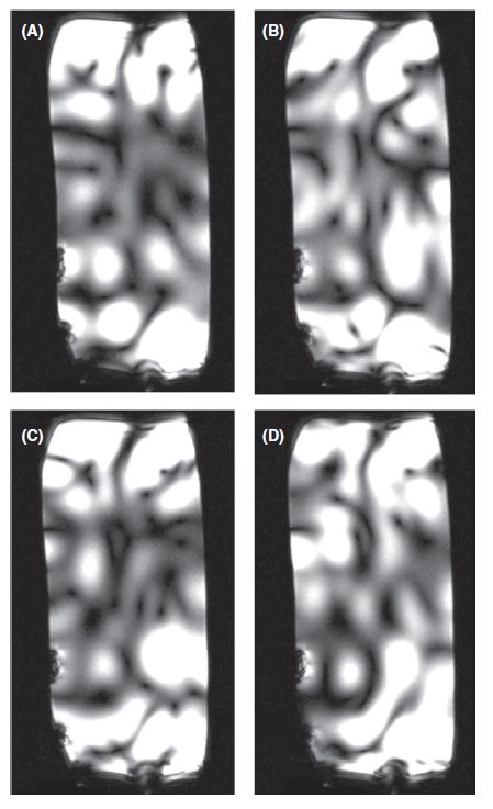
| Measured RF field uniformity maps across a saline phantom at ultra-high 10.5-Tesla field strength, demonstrating that the helical coil delivers consistent, usable signal across the imaging volume even at frequencies where standard coil designs struggle. |
|
|
|
|
Contactless Sensing for Orthopaedic Applications
|
|
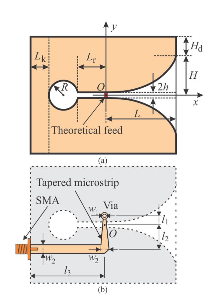
Schematic of the Vivaldi antenna's tapered-slot geometry and its compact microstrip feed network. The exponential curve profile and feed design were engineered to keep the antenna small while maintaining broadband, sensitive performance — key requirements for an implantable diagnostic sensor. |
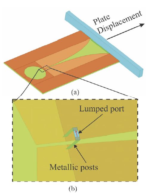
| A 3D electromagnetic simulation model of the Vivaldi antenna, showing a nearby metallic plate representing an orthopaedic implant component, plus a close-up of the antenna's compact feed mechanism. This model was used to predict how the antenna's resonant frequency shifts as the metal plate moves closer or farther away. |
|
|
|
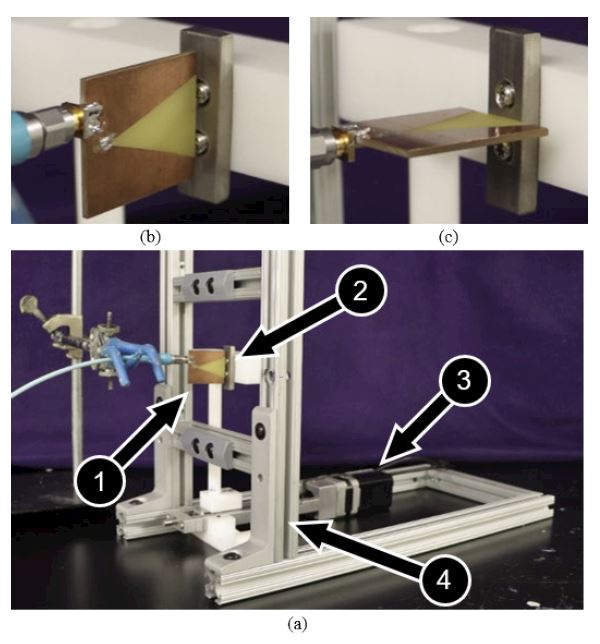
Photographs of the fabricated Vivaldi antenna prototype mounted in a benchtop test rig, shown aligned both parallel and perpendicular to a metal plate driven by a precision linear actuator. This setup recreates a clinically realistic implant-monitoring scenario to validate the antenna's sensing performance experimentally. |
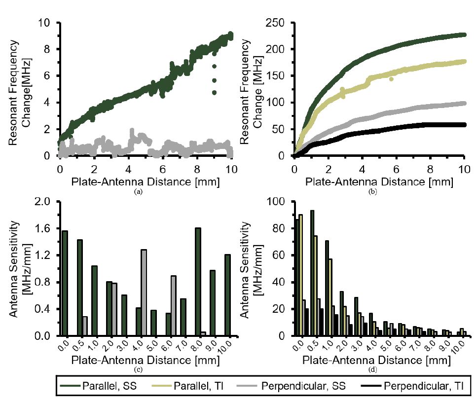
| Measured resonant frequency shift and sensitivity as a function of plate-antenna distance, comparing standard versus miniaturized antenna designs in parallel and perpendicular orientations. The results demonstrate that the antenna can detect implant displacements as small as fractions of a millimeter, supporting its use as a precise, contactless orthopaedic diagnostic tool. |
|
|
|
|
Power Amplifiers
|
|
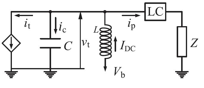
The basic Class-J amplifier circuit model, showing the transistor's current source, parasitic capacitance, and output matching network. This idealized schematic is the starting point for deriving closed-form efficiency equations that guide the amplifier's design. |
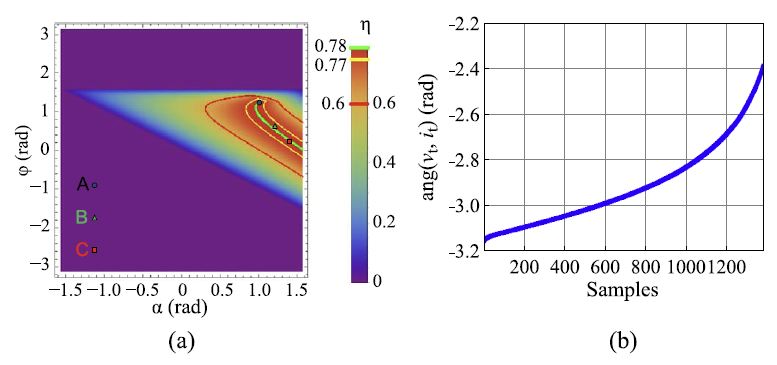
| A 2D efficiency map showing how drain efficiency varies with two voltage/current phase angles, with the ridge of near-80% efficiency highlighted in red. This plot is the core design tool: any point along the green line yields a desired predetermined efficiency, letting the designer trade off bandwidth and performance. |
|
|
|
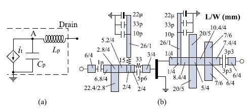
The transistor's simplified output equivalent circuit and the full fabricated amplifier layout, including the GaN HEMT die and matching network dimensions. This shows the path from theoretical model to a real, manufacturable RF circuit. |
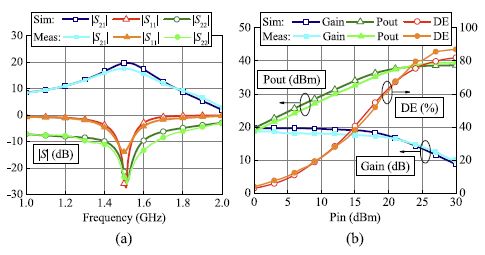
| Simulated versus measured performance of the fabricated 1.5 GHz amplifier: S-parameters across frequency, and gain, output power, and drain efficiency versus input power. The close match between simulation and hardware measurements validates the predetermined-efficiency design method. |
|
|
|
|
Large-Domain
Higher-Order
Finite
Element
Modeling
of
Microwave
Devices
|
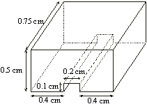 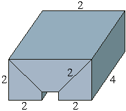
|
Largde-domain
higher-order
computational
approach
can
greatly
reduce
the
number
of
unknowns
for
a
given
problem
and
enhance
the
accuracy
and
efficiency
of
the
Finite
Element
Method
(FEM)
analysis
in
all
classes
of
applications.
This
approach
utilizes
higher-order
basis
functions
defined
in
large
geometrical
elements.
An
air-filled
rectangular
cavity
with
a
metallic
ridge
(on
the
left)
is
modeled
with
three
hexahedral
elements.
The
adopted
field-approximation
polynomial
orders
in
individual
directions
are
also
indicated. |
| Generalized
curvilinear
interpolatory
hexahedra
of
arbitrary
geometrical
orders,
adopted
for
the
approximation
of
geometry,
enable
excellent
curvature
modeling
(e.g.,
a
spheroid
on
the
right
is
sufficiently
accurately
modeled
by
a
single
curved
hexahedral
finite
element). |
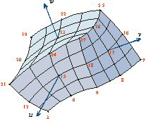 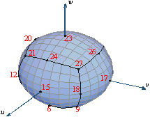
|
|
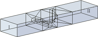
|
The
technique
provides
a
whole
range
of
element
shapes
(e.g.,
brick-like,
slab-like,
and
rod-like
planar
hexahedra,
as
well
as
spherically-shaped,
cylindrically-shaped,
and
elliptically-shaped
curved
hexahedra,
and
also
other
"irregular"
and/or
curved
hexahedral
shapes)
to
be
used
in
a
simulation
model
as
well.
(A
ten-element
model
of
WR-62
waveguide
with
two
crossed
cylindrical
posts
is
shown
on
the
left.) |
| The
hierarchical
curl-conforming
polynomial
vector
basis
functions
of
arbitrary
orders
enable
excellent
field-distribution
modeling
(e.g.,
10th-order
polynomial
field-approximation
in
the
three
parametric
coordinates
in
a
hexahedral
finite
element).
This
enables
using
as
large
as
about
2l
�
2l
�
2l
curved
FEM
hexahedra
as
building
blocks
for
modeling
of
the
electromagnetic
structure
(which
is
20
times
the
traditional
low-order
modeling
discretization
limit
of
l/10
in
each
dimension).
Calculated
reflection
coefficient
for
the
model
of
the
microwave
structure
shown
above,
with
optimal
orders
of
the
polynomial
field-approximation
in
different
elements
and
in
different
directions
in
the
range
from
2
to
5,
is
given
on
the
right. |
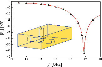
Calculated
reflection
coefficient |
|
|
|
|